Build Drones Part 1: DJI F550 Assembly and My Previous Research
Background: Why the DJI F550?
When deciding to build a custom drone from scratch, I chose to start with the DJI Flame Wheel F550 hexacopter. The primary reason for this choice is my extensive past experience with this exact airframe. I had previously used a DJI F550 platform successfully in my research focusing on the Use of Unmanned Aerial Vehicle for Multi-temporal Monitoring of Soybean Vegetation Fraction. Because I knew the F550 was stable and reliable for agricultural remote sensing from that project, it was the perfect baseline to begin building from.
In this post, I will document my experience revisiting the updated DJI F550 ARF kit, estimating its theoretical flight time, and conducting my first set of test flights and PID tuning.
1. Hardware Overview
Before the assembly, I had to get the right components together. Here is the final parts list for this hexacopter build:
- Frame & Propulsion: DJI Flame Wheel F550 ARF Kit v5. This kit includes the DJI E305 propulsion system (2312E 800KV CCW motors and 30A ESCs) pushing 9.4x5.0 inch propellers. Each motor can produce a maximum thrust of 850g using a 4S LiPo.
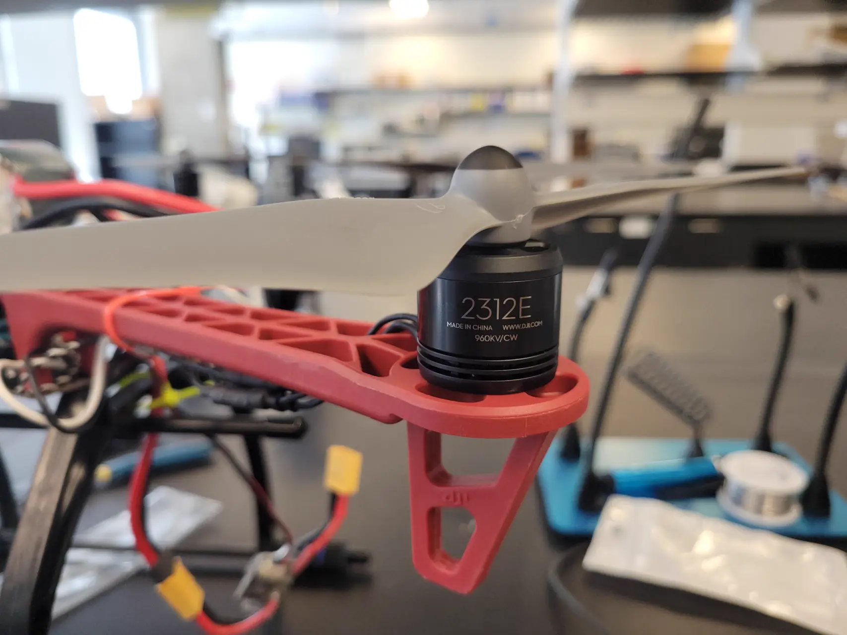
- Flight Controller: Pixhawk PX4 PIX 2.4.8 Flight Controller Set (includes GPS and 3DR Radio Telemetry).
- Remote Controller: Flysky FS-i6X 6CH 2.4GHz RC Transmitter with an FS-iA6B Receiver, paired with an FS-CVT01 voltage collection module to monitor battery health mid-flight.
- Battery: Zeee 4S 6200mAh LiPo Battery (and later a custom 21700 4S2P Li-ion pack).
2. Assembly of the DJI F550
The build process started with organizing the workspace and the components. The DJI F550 is a popular hexacopter frame known for its stability.
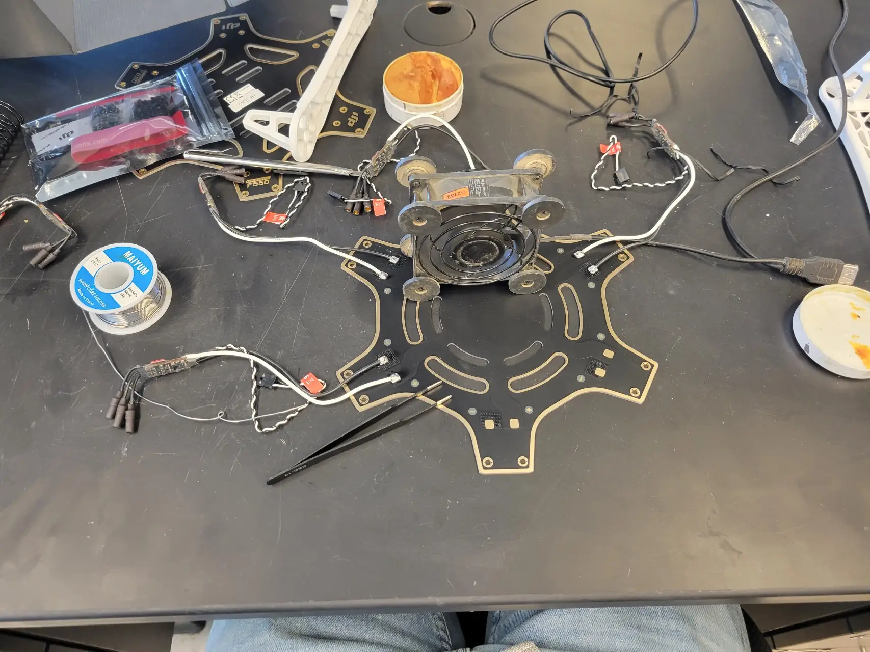
Soldering the Power Distribution Board
The F550 has a built-in power distribution board on its bottom plate. I carefully soldered the ESCs (Electronic Speed Controllers) and battery connectors to the board.
Frame Assembly and Transmitter Setup
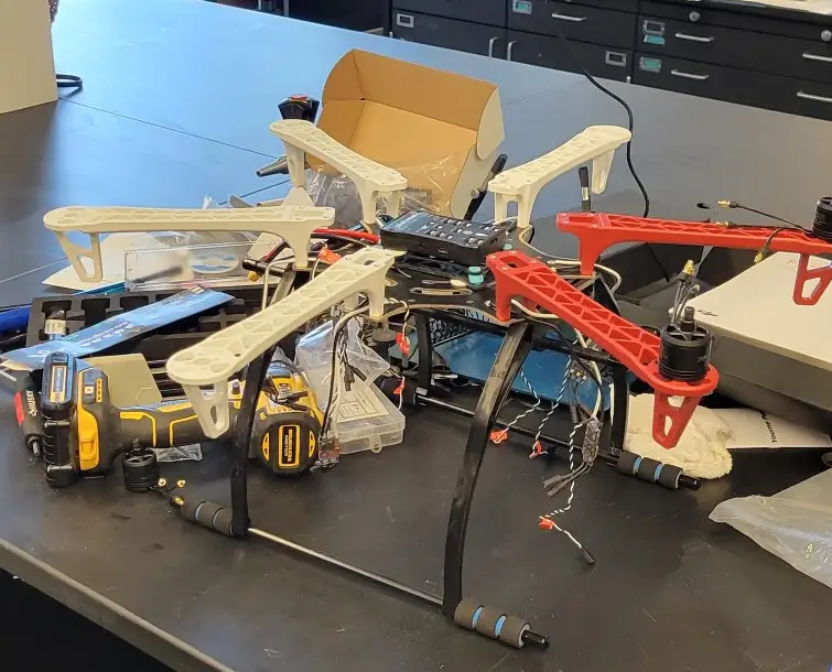
After the electronics were secured, I assembled the arms and mounted the motors, finishing the raw frame build.
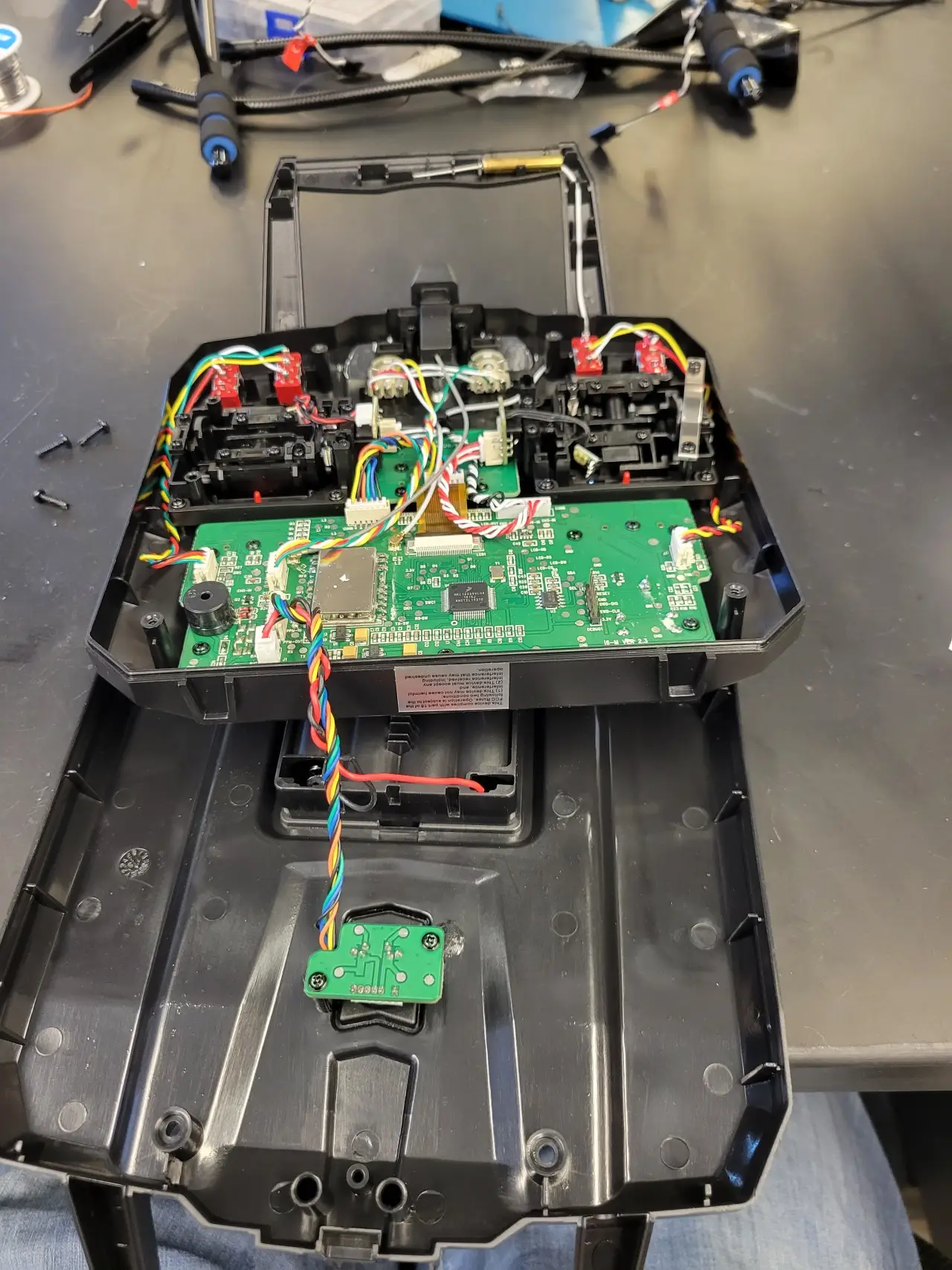
I also reconfigured my radio controller from Mode 1 to Mode 2 to match my preferred flying style.
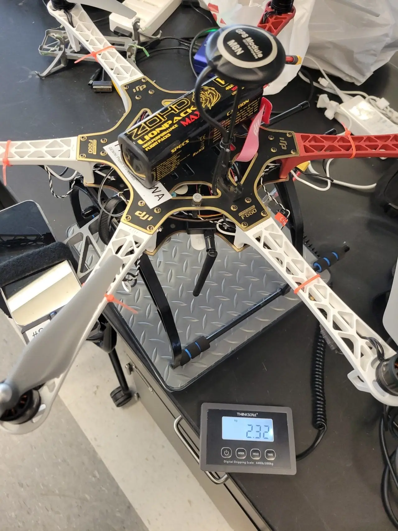
Finally, considering the full weight of the drone:
3. Flight Time Estimation using eCalc
Before flying, it’s important to estimate the safety margins for your battery capacity based on average amp draw and the system’s weight. Using eCalc with our assumed parameters (2400g AUW, 4S battery, 800KV motors, 9.4x5.0 props), I mapped out the theoretical hovering limits.
Here is the mathematical process for calculating practical multicopter flight times:
Example Calculation (Multirotor): Suppose the drone uses a 4S battery pack rated at 10,000 mAh (like the custom 21700 4S2P pack) and draws an average of 25 amps during flight.
- Step 1: Battery rating = 10,000 mAh
- Step 2: Convert to amp-minutes: $(10,000 / 1,000) \times 60 = 600 \text{ amp-minutes}$.
- Step 3: Current draw = 25 amps.
- Step 4: Maximum flight time = $600 / 25 = 24 \text{ minutes}$.
- Step 5: Always leave a safety margin! The 90% rule dictates landing when 90% of your capacity is used to prevent cell damage. The recommended safe flight time is usually calculated between a 40% and 70% safety factor, yielding about 10 to 17 minutes of safe flying.
Reference: LSU AgCenter Drones
4. Test Flights, AutoTune, and Diagnostics
October 25, 2023 - Initial Hover Test
The initial flight test went smoothly. The primary goal was to check hover stability, verify motor spin directions, and ensure the flight controller was responding properly.
AutoTuning PID Parameters
To lock in the stability, I used ArduPilot’s AutoTune feature. By bringing the drone into AltHold mode and triggering the AutoTune switch, the Pixhawk system systematically twitched the drone across the Roll and Pitch axes. It automatically computed the optimal Proportional, Integral, and Derivative (PID) parameters for this specific 2400g frame, drastically reducing wobbles.
October 31, 2023 - Endurance and Real-World Current Draw
A few days later, I conducted a longer flight test to analyze the real-world battery endurance.
Observations:
- Amp Draw: The F550 hovered at around 15A to 20A continuous. (Averaging roughly ~295 mAh consumed per minute).
- Max Flight Time Realization: Based on the current draw and the safe voltage limit (landing when the 4S pack reaches 14.0V under load, or 3.5V per cell), the maximum safe flight time was estimated to be only about 10 to 15 minutes.
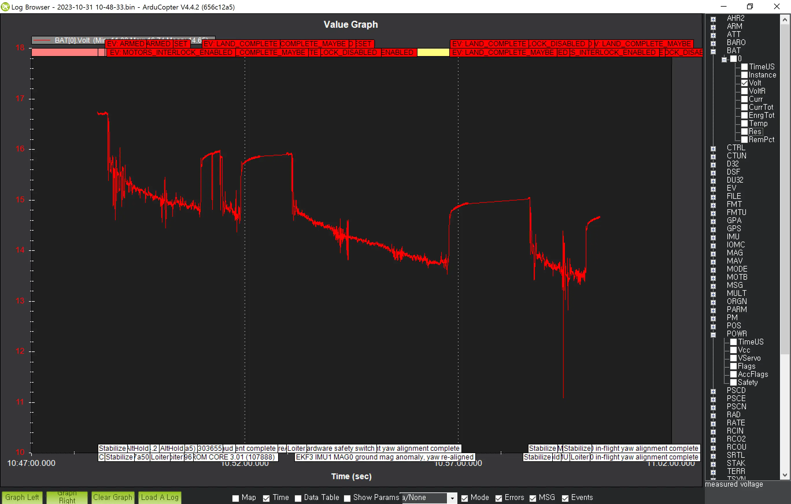
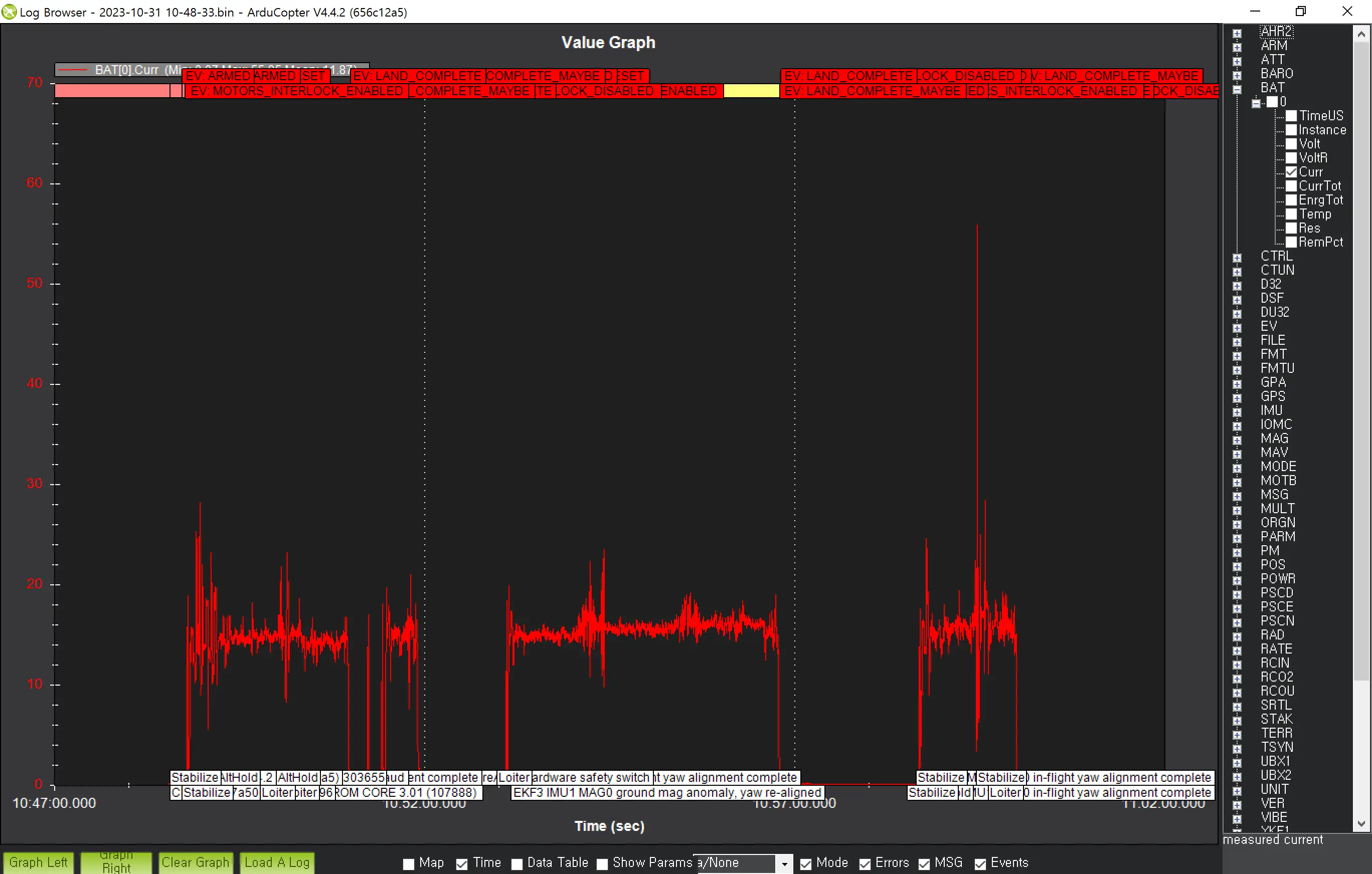
During this test flight, the battery capacity dropped aggressively. We also ran into a pre-flight “Battery fault” error that needed to be investigated caused by voltage sags under heavy dynamic load:

Conclusion
While the DJI F550 proved capable of stable flight and successfully completed its PID AutoTune, its 15-minute absolute maximum flight time proved to be insufficient for extensive scientific testing and heavy payload carrying.
Because of this, I’ve realized that I need an airframe with lower KV motors, larger props, and a higher capacity battery structure. This realization leads perfectly into the next phase: upgrading the drone entirely to the Tarot 650 Sport.